Architecture overview
Hyperplane is a platform that powers networking services like Network Load Balancer (NLB), NAT gateway (NATGW), PrivateLink, Gateway Load Balancer (GWLB), and Transit Gateway (TGW), and many other AWS services use it internally.
One AWS region has many Hyperplane clusters (a.k.a. Hyperplane cells) handling slices of workload. See Design Principles for details.

Nodes
Hyperplane nodes are just regular EC2 instances running in a VPC.
Flow tracker
Flow tracker is a horizontally scalable database that tracks all flows going through a Hyperplane cluster. It is custom built for flow tracking because no existing database solutions has the desired scale, latency and availability characteristics.
The data store maintains 1:1 redundancy of the flow state. When a nodes goes down in case of software deployments or failures, state is replicated to other nodes, repopulating the primary and secondary nodes for each connection involved.
Packet processor
Packet processor is a horizontally scalable layer that handles packet processing and forwarding.
The packet processing happens in user space.
Control plane
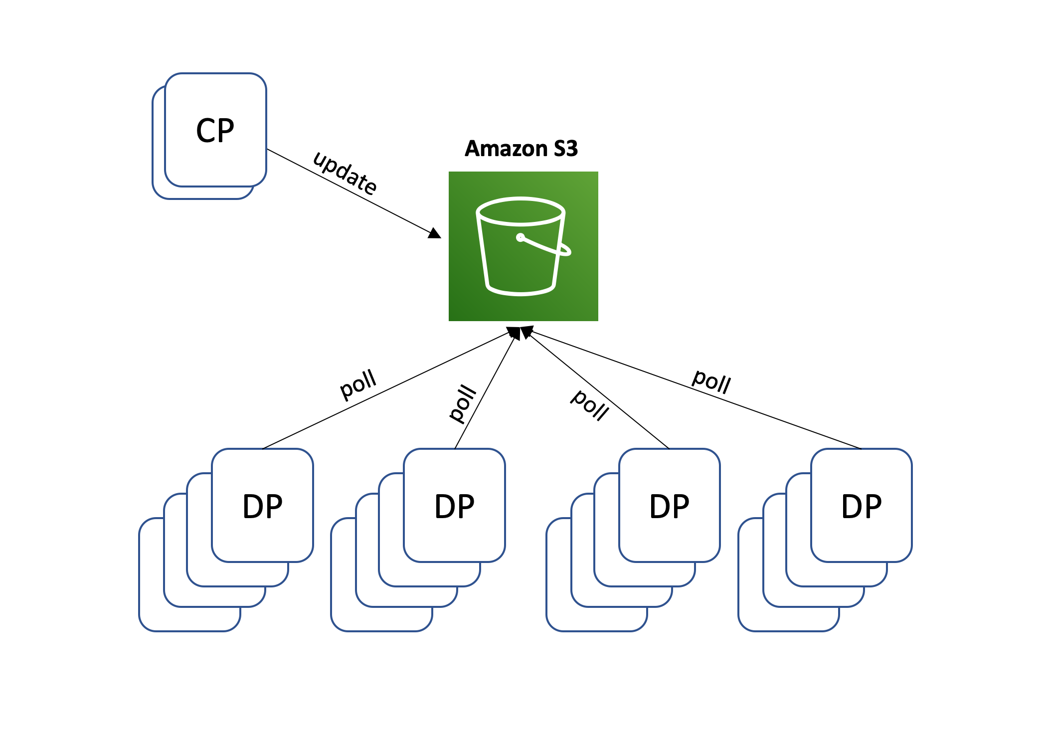
Control plane distributes configuration updates to flow trackers and packet processors, and manages Hyperplane capacity dynamically in response to change in demand by provisioning and de-provisioning EC2 nodes.
Continuous testing
AWS runs tests in each AZ continuously to monitor latency, availability and functional correctness.
Service monitoring
Hyperplane exports customer-facing metrics to CloudWatch via Kinesis.
Establishing a connection
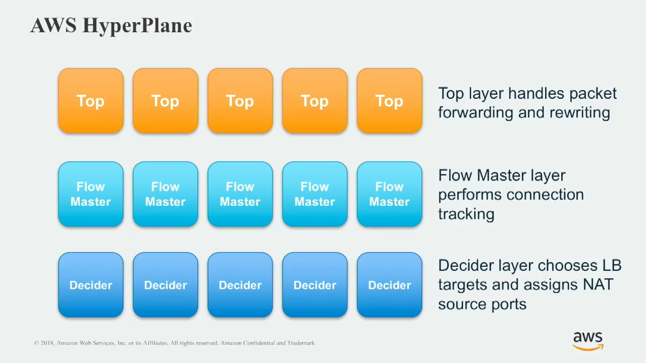
First, let’s zoom in and look at a more detailed architecture of Hyperplane. The packet processors are called Tops internally, and the flow trackers are composed of two components, Flow Masters and Deciders.
Their functionality is:
- Top layer handles packet forwarding and rewriting.
- Flow Master layer performs connection tracking.
- Decider layer chooses LB targets and assigns NAT source ports.

When a client on the Internet tries to establish a TCP connection to a public NLB:
- The client sends a TCP SYN packet to establish a connection with a NLB’s public IP address.
- The packets ends up on a Blackfoot Edge fleet, which rewrites and forwards the packet to a particular Hyperplane cell.
- When packets arrives at Hyperplane, the flow is hashed to select a Top. Likely with ECMP or similar protocols.
- The Top does not have state information about the connection yet, so it asks the primary Flow Master, selected by hashing, and runs through the backend selection process described below.
- The Top saves connection state in memory, rewrites and delivers the packet to the target selected, keeping the source IP and port.
- The target receives the packet, and its Nitro controller remembers to redirect packets to the client IP and port back to Hyperplane.
- The target sends a SYN-ACK packet, which is routed to the same Hyperplane cell via Nitro and VPC networking.
- The flow is again hashed to select a Top. However, the return path is likely going to hit a different set of nodes in all three layers because the hash ends up differently when you reverse the source and destination. AWS calls it hashing on an ordered flow basis.
- The Top selected forwards the packet to the client, and the TCP connection is established after 3-way handshake completes.
Once the flow is established, all Tops involved remember the connection, so only the Top is involved in normal operation. In this mode, the performance penalty is on the orders of tens of microseconds.
Backend selection
Packets are chain-replicated between packets processors and flow tracker nodes, such that there is no buffering or retries when packets processors wait for a decision from flow trackers.

The chain also implements 1:1 redundancy. A pair of secondary decider and flow master is selected with a second set of hashes.
Design principles
The primary design goals are:
- Cost efficiency (compared to fleets of commercial load balancers)
- Scalability
- Availability
- High throughput
- Long-lasting stateful connections (keep track of connections for years, e.g. for EFS connections)
- Fault-tolerant
Constant work
The system should be simple and consistent, especially when facing failures. There should be as few modes of operations as possible, to avoid combinatorial explosions of complexity.
One example is that cells have a fixed design capacity to test against. When scaling up, more cells are deployed instead of scaling up a particular cell.
Another example is the S3 Configuration Loop, as shown below.
Design for failures
Fail fast
No packet buffering or retries. Rely on TCP retransmission from the clients.
Self-healing
Packet processors sends periodic heartbeats to flow trackers to update flow information, so that a failure in the redundancy of flow trackers can be recovered from and doesn’t break existing connections.
In many occasions, automation system can mitigate customer impact quickly in respond to an alarm.
S3 configuration loop

AWS Hyperplane nodes fetch, process and load configuration files from Amazon S3 every few seconds, even if nothing has changed.
The configuration file is sized to its maximum size right from the beginning to ensure the system is always processing and loading the maximum number of configuration changes.
Such that,
- The control plane scales independently of the data plane fleet, and a storm of configuration changes does not overload the data plane.
- if AWS Hyperplane nodes are lost, the amount of work in the system goes down, not up.
Shuffle sharding
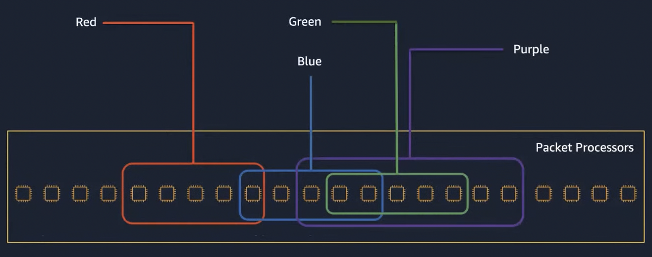
AWS uses shuffle sharding for heat management, as shown in the diagram below.

With 100 nodes, there is only 2% chance for 5-node random selections to overlap more than 1 node. AWS also employs algorithmic measures to avoid overlap of more than 2 or half of the nodes between two tenants. This provides good isolation between tenants.
Cell-based
Hyperplane is a cellular and zonal service, which means that Hyperplane has its own control plane and data plane for each availability zone (AZ), and within each AZ Hyperplane operates a series of isolated cells, including a control plane for each cell. This limits blast radius and prevents single point of failure.
Performance
As of 2018, a single cell of Hyperplane can support terabits per second of throughput, hundreds of millions of connections, and tens of millions of transactions per second.
Symmetric flows
Flows have symmetric network path (i.e. no DSR) to enable collecting metrics from traffic in both directions on Hyperplane nodes. In case of NATGW, the packets have to be rewritten in both directions, so all packets has to go through Hyperplane.
Going through a Blackfoot or Hyperplane node have almost the same latency, so there is little negative impact.
Security
VPC mappings are abstracted away from Hyperplane nodes and the mappings are built and enforced in hardware instead. This protects Hyperplane from certain vulnerabilities like spoofing attack.
CI/CD
Hyperplane’s development model is CI/CD. The CI/CD system extensively tests code as part of the deployment pipeline, and when the monitoring system detects a failure, rolls back the deployment automatically to the last know good version of that code.
History
Before Hyperplane, AWS have also built a custom-made load balancer for S3. Hyperplane is based on the architecture of the S3 Load Balancer. S3 did not migrate to Hyperplane, so don’t worry about circular dependency here.
The chronological order of services built on top of Hyperplane is as follows:
- EFS (2015)
- NATGW (2016)
- NLB (2017)
- PrivateLink (2017)
- and more
References
- https://aws.amazon.com/builders-library/avoiding-overload-in-distributed-systems-by-putting-the-smaller-service-in-control/
- https://aws.amazon.com/builders-library/reliability-and-constant-work/
- https://www.youtube.com/watch?v=8gc2DgBqo9U&t=2066s (2017)
- https://www.facebook.com/atscaleevents/videos/networking-scale-2018-load-balancing-at-hyperscale/2090077214598705/ (2018)
- AWS EC2N Hyperplane: A Deep Dive https://www.youtube.com/watch?v=GkYGo1M3vyc (2021)